Small object SfM photogrammetry#
Malte’s rock sample and digital measurements#
The various tips and tricks learned in the previous sessions can not only be applied to human-and-larger-scale objects, but also to objects only centimetres tall. In fact, smaller objects such as rocks make for a great way of learning SfM-photogrammetry.
A good example of a digitised handsized sample is Malte’s mineral below, which has been digitised to scale through use of ground control points.
SketchFab 3D model
Sadly, SketchFab does not (yet?) have distance querying built-in to the frontend. However, SketchFab Labs does provide such a feature. Either access it through the URL link below, or use the embedded iFrame to search, load and measure Malte’s Rock sample from within this page.
https://labs.sketchfab.com/experiments/measurements/
SketchFab 3D model (Verification)
Verification of your data is key to whatever you do in life. As such, why not ask Malte for the original rock sample and compare digital vs real dimensions?
You first need to load Malte’s rock sample into the SketchFab instance by clicking LOAD 3D MODEL. In the popup, either search Rock Sample Malte or click FROM URL and paste the URL you copied from below:
https://sketchfab.com/models/b2cb2ad336dd402eb3dc4222bb03d4bd
By clicking two points on the model, the Distance table updates and shows you a unitless measurement. We however know that Malte’s rock sample has been georeferenced in metric units. By increasing the multiplier to 100, we then turn the measurements to centimetres.
Digitising hand-sized samples#
Betlem et al., [BBO+20] present an effective means to digitise hand-sized samples at their respective scales. While the paper focuses on drill core samples, the same methodology can be used for most hand-sized samples from the field, minerals (e.g., Malte’s mineral), and other object, with and without GCPs to ensure correct scaling.
In short, the method relies on acquiring at least three photo haloes (i.e., 24-36 object-centred photos) of an object, in between which the object’s orientation has been changed (e.g., from normal position to upside-down to flipped 90 degrees). The easiest way of doing this is by using a well-lit round table, which allows a fixed rotation between each of the photos for a specific orientation. Furthermore, if one of the orientations contains GCPs, the resulting hand-sized sample model is automatically scaled correctly.
Lecture
101 to digitising handsamples#
In a nutshell, successful digitisation of small hand samples can be summarised as follows:
Target-images should be offset by no more than 15 degrees,
and the target’s orientation should be changed at least two times (=> 3 photo haloes).
The target should cover the full frame of the image,
with the entirety of the target kept in focus.
Enough light (i.e., minimal shadows) and correct colours
Focus & aperture#
Given the proximity to smaller handsamples (centimetres versus (deca)metre scale for outcrops), the in-focus depth range of the image is important. Optimally, the entire object should be in focus, to enable accurate correlation of the entire object across multiple images, thereby increasing the final quality of the models.
The impact of changing a camera’s aperture value on the focus/sharpness throughout the acquired image is shown in Fig. 42.
Fig. 42 A computer animation showing the effect of how aperture change affects the focus area of the image [].#
The largest in-focus field of depth therefore corresponds with the smallest aperture size (or largest f-number). This is something we should thus aim for when configuring our cameras.
As seen in Fig. 43, decreasing the aperture coincides with a reduction in light, and therefore requires either longer exposure times or a brighter imaging location.
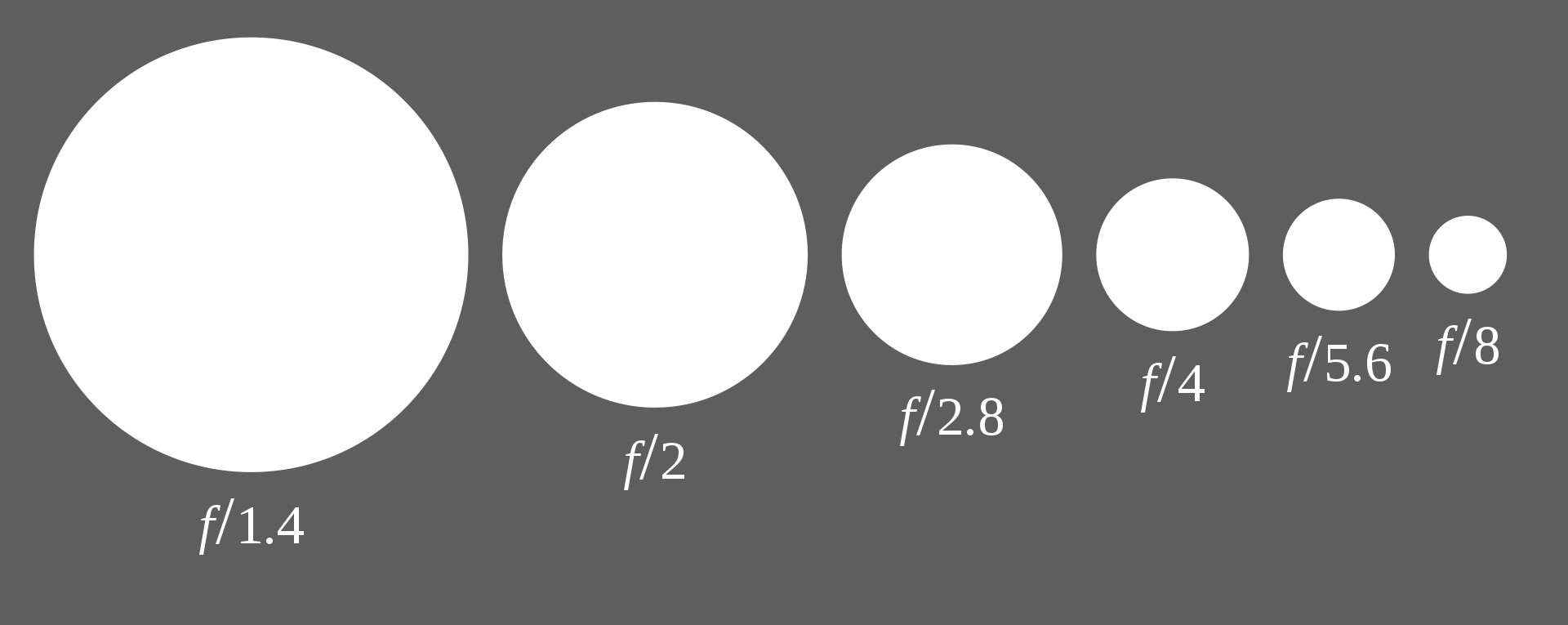
Fig. 43 Aperture sizes and related f-numbers. Going left to right, each circle is about a factor two smaller than the previous [].#
A tripod, exposure settings and colour diagrams#
Longer exposure times in a bright environment have the risk of several things, most notably introducing blur by moving the camera, overexposing the targets, and/or bleaching the colours.
First and foremost, image acquisition of handsamples should always use a tripod. Only a tripod keeps the camera exactly in place while taking an image, therefore preventing any blurring. For the same reason, a remote trigger is preferable.
When it comes to lighting, the object should be lit uniformly from all sides to prevent shadows and texture-colour change as a result of the lighting. Further, knowing the temperature of the light allows one to specify the light temperature as an acquisition parameter, which should compensate the colour adjustment in the final photos and result in True Colours.
True Colours
Capture a colour card in the background of your sample to adjust the colour balance as part of post processing. This works exceptionally well when coupled with raw imaging and can be used in conjunction with the light temperature parameter.
Capturing usable images: the Exposure triangle#
The aperture, shutter speed and ISO are recurring parameters of importance and key to data acquisition in the field and in the lab. In particular, they work together to create an exposure and affect your captured image in different ways. This can be visualised through use of the exposure triangle [Exp17].
Aperture#
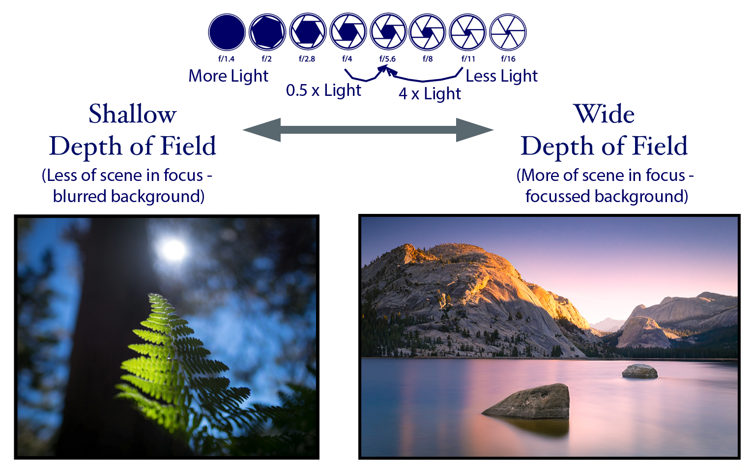
Aperture affect how much light passes through the lens, and, with it, the depth of field of the image [Und17]. Aperture is typically measured in f-stops, with smaller numbers meaning more light and larger numbers less light that hits the sensor. When you open your aperture (i.e., lower number, see (Fig. 44)):
more light hits the sensor
depth of field decreases.
Shutter speed#
Your camera’s shutter governs the duration that light passes through and is captured by your camera’s sensor. The amount of time is typically listed in seconds, and each step on the shutter speed scale will give you half or twice the amount of light. All light captured by the sensor over the amount of time (“acquisition time”) is averaged to give rise to a captured image. Shutter speeds that result in longer acquisition times, thus allow for more light to hit the sensor, and thus result in brighter images. Secondly, capturing movements within the acquisition time will result in motion blur. Some additional examples of how to deal with shutter speed are found in e.g. [Shu17].
ISO#
The ISO number describes how much the processor in your camera amplifies the light collected by the sensor. It is in a sense an indicator for how much the image is altered to produce a correctly exposed image. As with shutter speed and aperture, each step on the ISO scale doubles or halves the camera’s sensitivity. However, as it increases the camera’s sensitivity, it also introduces noise! It is thus always advised to keep the ISO as low as possible.
Working the triangle: The Rule of Equivalent Exposures#
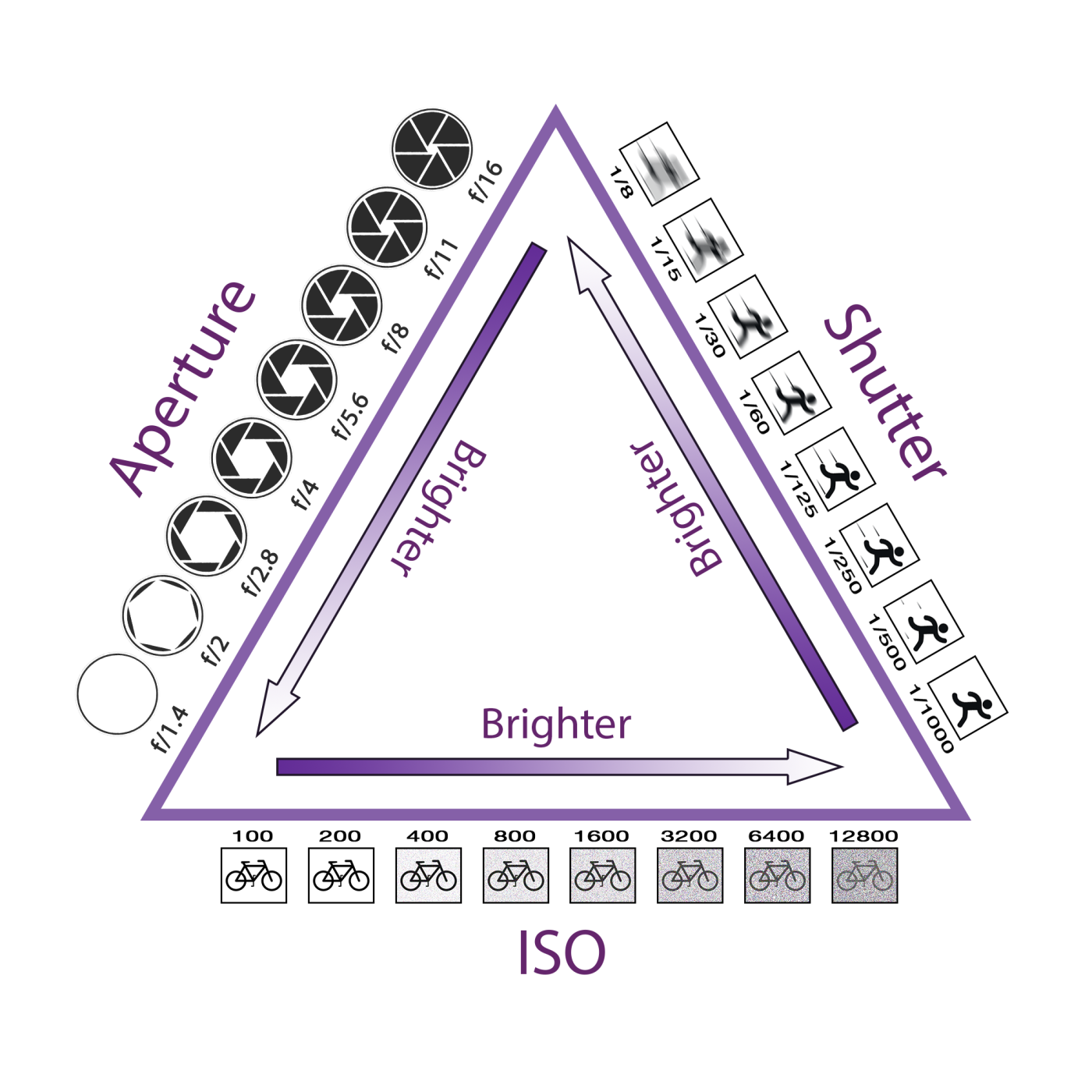
Exposure and capturing images with the right settings thus comes down to an interplay between the ISO, shutter speed and aperture values [Exp17]. Each click or stop-change in either of them halves or doubles the amount of light that reaches the sensor. Thus, if one action cuts the light by half, then you must double it in another to retain the same level of brightness in your captured images.
Haloes, arches and photo rings#
A good camera setup further contributes to consistency in the capturing process. Ideally, the sample should be imaged with sufficient overlap between images. Each of the haloes or photo rings in Fig. 46 represents this, with equal distances between the images in each ring.
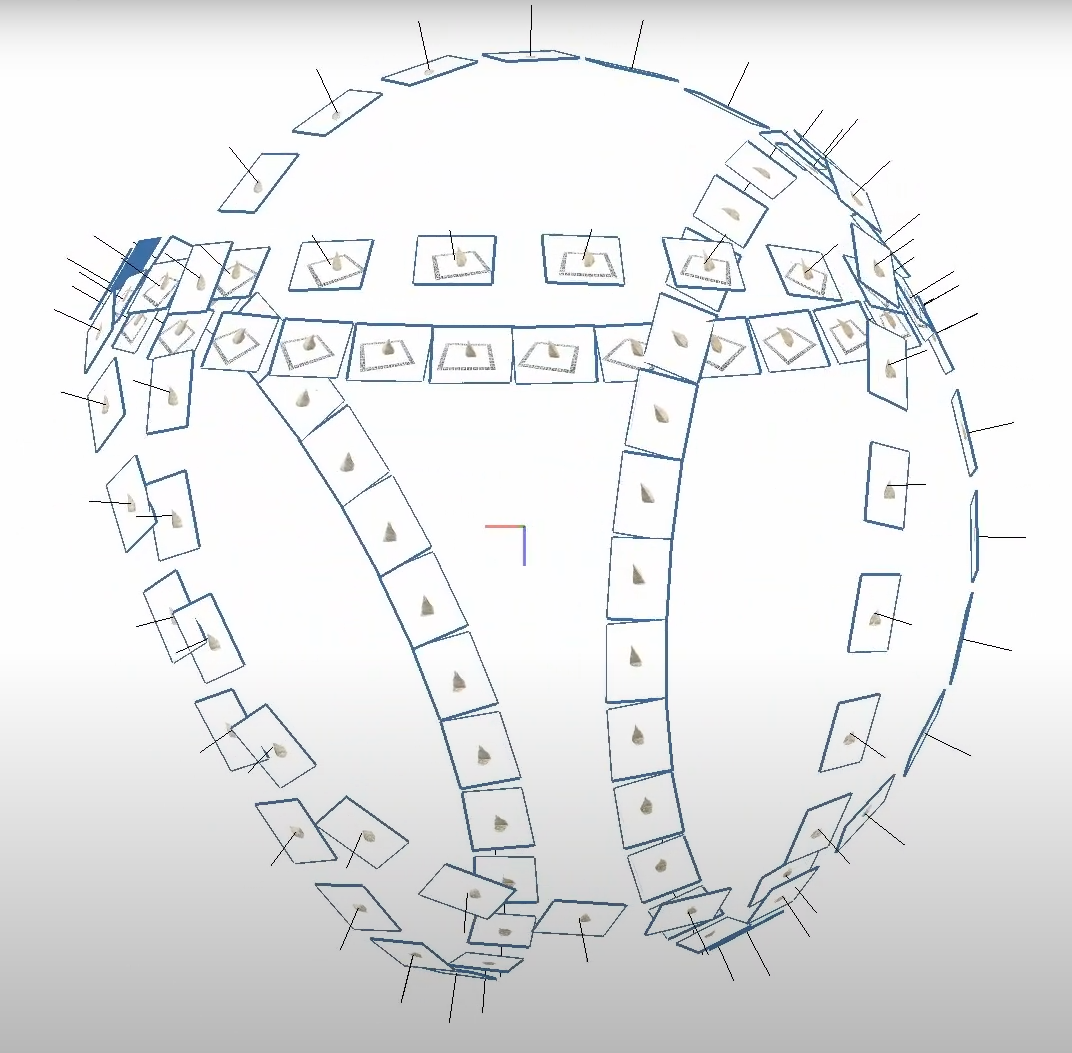
Fig. 46 Haloes around the sample (centre point). Each halo comprises all the photos taken of the sample in a specific orientation, meaning the sample shown has been imaged in four distinct positions. Within a halo each image should be equally spaced; if not, something has possibly gone wrong either during acquisition (or photo alignment), and needs checking.#
Fig. 46 has four rings in total, which means the sample has been imaged on four sides. Digitisation usually only succeeds when the sample is imaged in three distinct orientations, usually in top-down, down-top orientation, and a side-ways orientation that provides overlap between top-down and down-top orientations. Each additional orientation increases the confidence and success rate of the final digitisation.
Turntable support
We have access to a FOLDIO360 (lit) turntable at UNIS. The Foldio360 Tutorial details its use and allows you to automate a large part of the acquisition process.
Scaled models
By including ground control points (GCPs) in a single orientation (as per the GCP exercise), you can easily georeference the samples to their real-world scale. However, make sure to only do so for one (1) orientation, as GCPs are considered absolute reference points during processing and take precedence in aligning (or misaligning) your images!