
SfM photogrammetry#
Lecture#
Overview#
Structure-from-Motion photogrammetry (or SfM photogrammetry for short) allows you to digitise objects using nothing more than a camera, sufficient data storage, and enough processing power.
The video below provides a short and concise overview of how this process takes place, as well as the main steps that are involved in the digitisation of objects to their digital counterparts.
Lecture
Structure-from-Motion photogrammetry#
SfM photogrammetry implements (some of) the principles that we humans use to perceive the three-dimensional world around us. As an observer moves around, the surrounding objects move different amounts based on their distance from the observer, providing additional information on the depth/distance of individual objects. Had the observed not moved around, it would have been impossible to estimate the 3D coordinates of objects within the scene, yet alone to fully understand the entire 3D scene. After all, by looking at any given object from a single direction, the 3D scene effectively becomes a 2D image, which inherently does not have any data on depth.
Similar to how line of sight is used by humans to perceive depth, computer algorithms can establish a line of sight to key points on an object for different views (Fig. 2). Where different lines of sight intercept, an estimate of the 3D coordinates of a given point is found that can be combined with other estimated point coordinates to form a point cloud.
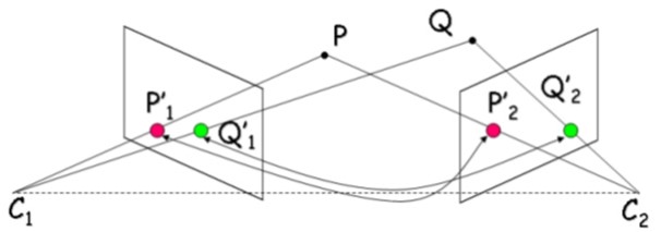
Fig. 2 Perceiving depth by tracing lines of sight from different viewing angles. Image from [HumboldtSUniversity16].#
Increasing the amount of lines of sight automatically results in a higher confidence of the 3D coordinates of the associated point. It is therefore common to not just use two or three 3D images, but rather a series of dozens, hundreds, and even more 2D images to reconstruct a 3D structure of a scene or object.
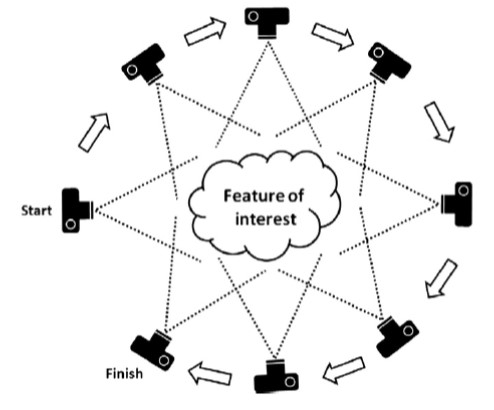
Fig. 3 Capturing an object from many angles with sufficient overlap between images is a must for usable output. Image from [WBG+12].#
Preferably, the images each feature a high degree of overlap and are taken from different angles (Fig. 3) to narrow down the margin of error of the coordinate estimates. Interestingly, modern algorithms do not only calculate the point coordinates - they simultaneously calculate the original camera locations; amazing, no?
This is, however, only the first step. Once the camera positions are known and a hand full of key matching points are estimated, the sparse point cloud (i.e., point cloud with only few key points) can be turned into a dense point cloud (i.e., every unique feature on the 2D images is turned into a unique 3D point).
Seeing as the points contain a Z or elevation component, the points can then be used to construct digital elevation models (DEMs), representing height information without further defining the surface.
One can also connect neighbouring points (coordinates along with other information such as colour, normal vector, etc., called verteces) to create edges; combine edges to create faces; combine faces into polygons and surfaces in a meshed model (Fig. 4).
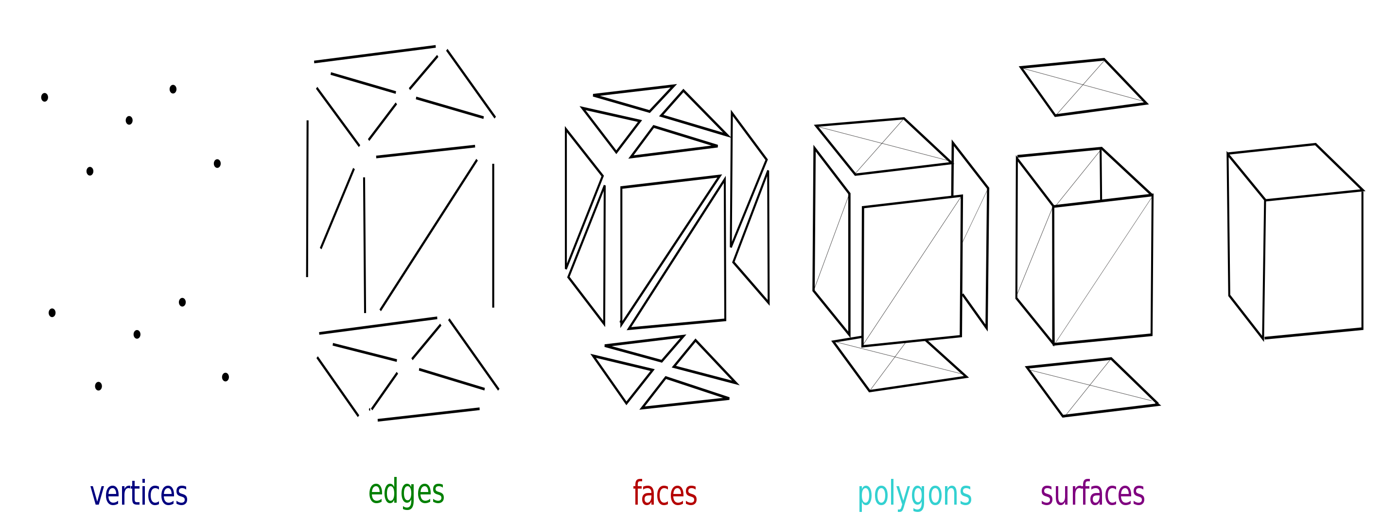
Fig. 4 Capturing an object from many angles with sufficient overlap between images is a must for usable output. Image from [Lobsterbake09].#
The meshed model is effectively the digitised outer shell of the 3D scene that was captured on camera. Ddigital outcrop models (DOMs) is the term given to meshed models (often with texture, i.e., colouring) of geological outcrops. An example of a DOM featuring the folding observed near the top of the Janusfjellet mountain on Svalbard is shown below:
Further reading
Westoby et al. [WBG+12] put together an excellent overview on the use of SfM photogrammetry in the geosciences, which is a recommended read for the interested reader.