
Ground control points (GCPs)#
Ground control points (GCPs) are locations that we can track with high precision and accuracy between the targeted object and a selection of our photos. We can use these to provide “exact” real world coordinates to our reconstructed models, as well as to determine the accuracy and impact of processing parameters.
In a mapping survey, GCPs are points which can be precisely pinpointed. This precision not only applies to the points themselves, but can also be interpolated to the mesh between GCPs. It is therefore possible to accurately map large areas with only a handful of precisely known coordinates (up to sub-metre levels!).
Geo-location accuracies
We distinguish 3 different scenarios when it comes to geo-referencing:
Horizontal - i.e., measuring longitude, latitude
Vertical - i.e., measuring altitude
Full - i.e., measuring longitude, latitude, and altitude
Given the way GPS works, vertical accuracies are usually worse than horizontal accuracies (often by more than an order of magnitude). Seeing as most handheld and built-in GPSs have a horizontal error of at least 1 metre, the corresponding vertical error may be large enough to prevent accurate correlation to the real world.
built-in GPS
The images taken from drones or GPS-equipped cameras store the image location in the image’s metadata. Metashape automatically imports this upon loading. Do remember, however, that built-in GPSs still have quite large errors compared to differential GPS and similar.
When do we need GCPs?#
GCPs are essential when you need high global accuracy (or absolute accuracy) and when you need to verify the accuracy of the final models.
Applications include:
terrain mapping (contour map, digital terrain model, etc.)
geotechnical surveys (e.g., land titles, other assessments)
volume measurements
Only when the area is small and we do not care about absolute accuracy (i.e., only relative accuracy is important) can we omit GCPs. This is e.g. the case when we want to compare elements within the same models without relating these to real world properties.
GCP design#
In general, ground control points must be sharp, well defined, and positively identifiable on at least a sub-selection of photos. In many cases it is therefore a rule of thumb that markers used as GCPs should be unique.
We generally differentiate between artificial and natural GCPs. Here, however, artificial strictly means that a marker or GCP was specifically designed and placed for the survey. Natural markers include e.g. terminus of a sidewalk, sharp corner of a parking spot, a unique landscape feature (e.g., rock, peak), etc. Artificial markers’ unique appearance makes misidentification less likely, though comes at the cost of extra work and expense as artificial markers have to be manually set up prior to image acquisition.
So, when implementing GCPs, what should we keep in mind?
Unique GCP shapes#
While technically not a requirement, it is always preferred to be able to differentiate GCPs based on uniqueness of the marker. That means, in its most simplistic form, one could get away with a simple four-member marker-set.
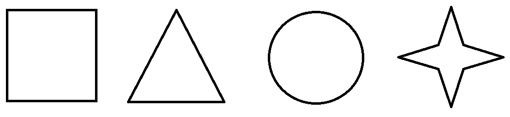
Fig. 30 A basic set of four unique markers that can be used as artificial markers.#
While identification of the shapes should be rather straightforward, some troubles are also easily foreseen. For instance, being highly symmetrical, where would you measure the real world coordinates on the triangle? And are you 100% confident that you would be able to pick the same corner? And what about going for the centre of the shapes? Would you be able to eyeball placement of the measurement and be within the error associated with dGPS (i.e., mm-scale errors in total)?
Addressing these shortcomings are modern GCPs that implement lessons learned from the barcode. With each subsequent marker in a set slightly differing, and therefore considered unique, these synthetic markers are great for use as GCPs.
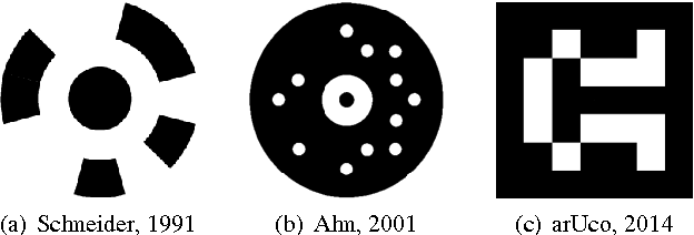
No longer featuring a plane of symmetry, one can now certainly select a point where the real world coordinates can be measured and later the corresponding pixels in the photo can be selected.
Be consistent!
Make sure to always be consistent when dealing with point coordinates. If you decide to measure the first marker in the top right corner, then make sure to always measure the top right corners for each subsequent marker.
Computer readability#
The standardised uniqueness of binary fiducial markers furthermore allows for automisation of the marker detection step. While not an issue when dealing with just a handful of photos, highly detailed surveys quickly expand the photo collection to hundreds, if not thousands, of photos.
While Agisoft Metashape provides a set of GCPs internally, one of the most popular marker sets is the ArUco library [GarridoJuradoMunozSalinasMadridCuevasMarinJimenez14]. In addition to exhibiting a standardised uniqueness, the ArUco-based markers are square markers and thus preferred as a single marker provides enough correspondences (i.e., its four corners) to obtain the camera pose in augmented reality applications.
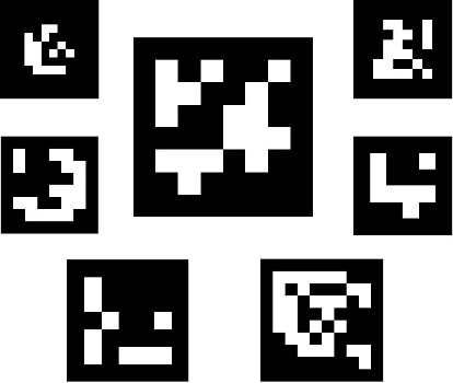
Fig. 32 Example of ArUco marker images [GarridoJuradoMunozSalinasMadridCuevasMarinJimenez14].#
Python-based automated marker detection
ArUco markers (50x50 cm) printed on canvas are available for use in the UNIS Arctic Geology department. Marker detection hereof can be done by using the scripts described in the Python-automisation chapter.
GCP size#
As a rule of thumb, a GCP marker should be fully identifiably on a photo by nothing more than the naked eye. This means that the size of the GCP markers should scale with the imaging distance, i.e., the distance between the camera lens (albeit in hand, UAV) and the imaging target.
Placement of GCPs in terms of highest accuracy#
An extensive review on the accuracy of GCPs types is conducted by [MartinezCarricondoAgueraVegaCarvajalRamirez+18] and [], and we here only focus on the take-home messages. These conclusions are based on an accuracy-assessment that seeks minimal root mean square errors (RMSEs) for the GCPs’s longitude, latitude, and altitude.
Prior to implementing GCPs, one always has to assess the need of precision and accuracy in terms of cost, i.e., time. In a timeless setting, one could set up an infinite amount of GCPs (Fig. 33, top row) and obtain the smallest GCP RMSEs in each direction. However, when time is of the essence, there appears to be a cut-off point at which the introduction of an additional GCP does not warrant the additional time it takes to set it up. As a result, efficiency can be gained by reducing the number of GCPs (Fig. 33, second row).
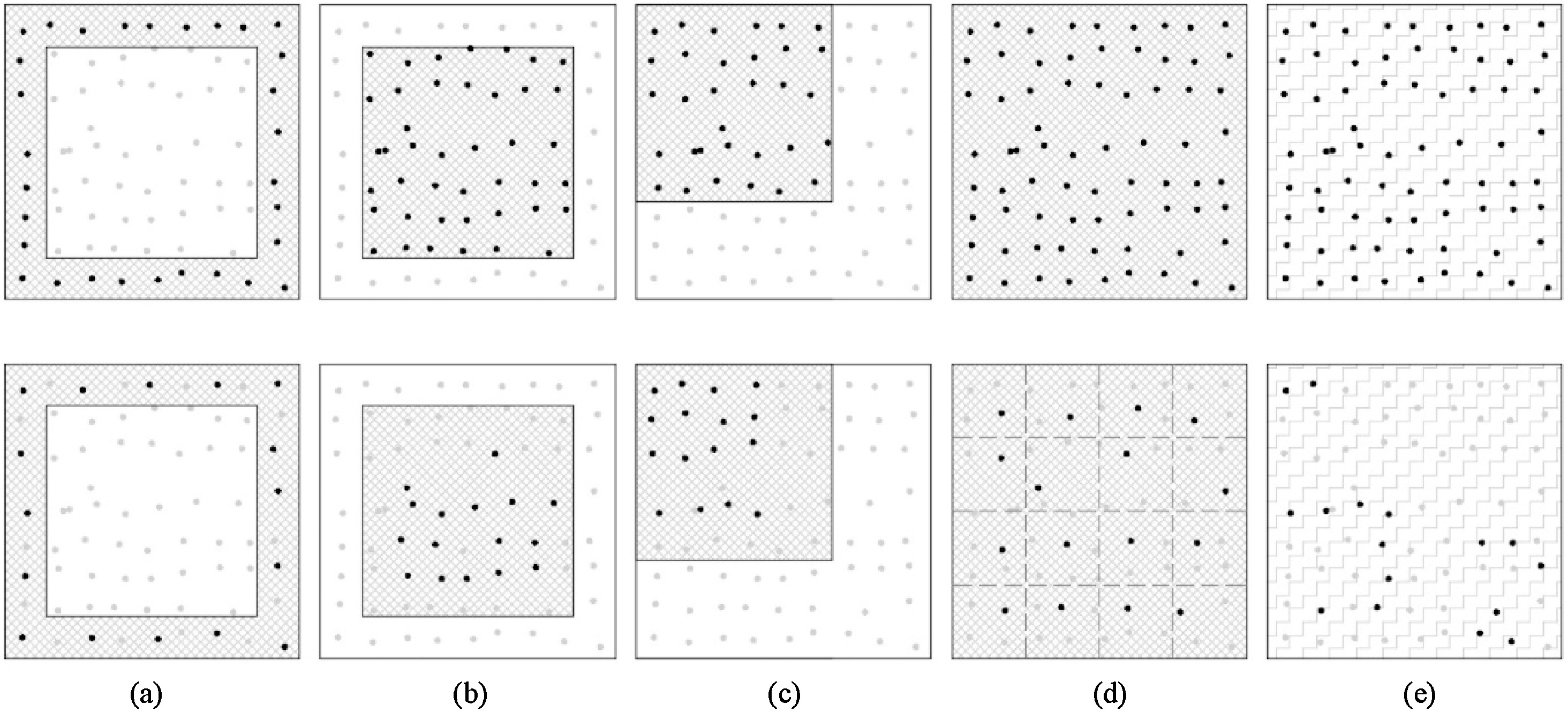
Fig. 33 Five different GCP distribution types and an example for the combination of 16 GCPs (second row). (a) edge distribution, (b) central distribution, (c) corner distribution (equivalent for all four corners), (d) stratified distribution, (e) random distribution. In general, a combination of the edge and stratified distribution (d) gives rise to the lowest overall errors [MartinezCarricondoAgueraVegaCarvajalRamirez+18].#
Placing the GCPs around the edges and in a stratified manner throughout the survey area results in the lowest overall errors. Therefore, best accuracies are achieved (1) placing GCPs around the edge of the study area, but it is also essential to (2) place GCPs inside the area with stratified distribution to optimize vertical accuracy [MartinezCarricondoAgueraVegaCarvajalRamirez+18]. As for the optimal number of GCPs in the stratified interior, try to aim for a density of around 0.5-1 GCP per hectare to minimise altimetry errors, and make sure to place GCPs throughout the entire altimetry-interval, e.g., covering both ridges and valleys.
Hand-sized samples
GCPs are also implemented for the digitisation of hand-sized samples. Then, however, it is suggested to only place GCPs along the edge.
Finally, always make sure to properly fasten & secure your GCPs. A moving GCP is essentially useless, and likely to give rise to major positional errors in the final models.